Language
 How Does the Woodward Marine Governor Test Bench Work?
How Does the Woodward Marine Governor Test Bench Work?
 As the "brain" of a ship’s main engine control system, the marine governor is responsible for adjusting the engine speed precisely according to the bridge’s throttle commands, directly safeguarding the ship’s navigation safety and operational efficiency. Woodward, a globally renowned leader in power control solutions, produces marine governors known for their high reliability and precision. However, to ensure these governors perform flawlessly under the harsh marine conditions—such as extreme temperatures, heavy loads, and frequent speed changes—a specialized Woodward marine governor test bench is indispensable.
This test bench is designed to simulate real-world operating scenarios, validate the governor’s performance, and detect potential faults before installation. In this blog, we will break down the core components and detailed working principles of the Woodward marine governor test bench, helping you understand the precision behind marine power control.
First: The Core Role of Woodward Marine Governor Test Bench
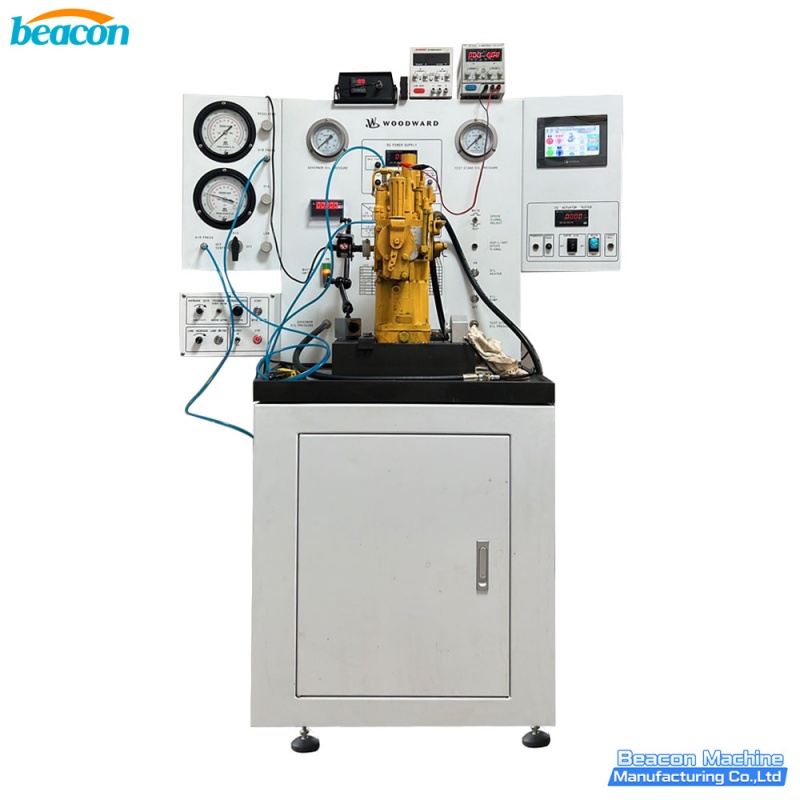
A Woodward marine governor typically consists of key components like speed sensors, control units (e.g., MCG-402), actuator drive units (ADU), and servo motor actuators. Its core function is to maintain stable engine speed by regulating fuel supply in response to load changes. The test bench’s primary mission is to replicate the interaction between the governor and the ship’s main engine in a controlled laboratory environment. Specifically, it verifies:
Accuracy of speed regulation and response speed to throttle commands.
Stability of the governor under different load conditions (e.g., light load, full load, sudden load changes).
Reliability of signal transmission between the control unit and actuator.
Fault tolerance and self-adjustment capabilities of the governor system.
By conducting these tests, the bench ensures that the Woodward marine governor meets the strict operational requirements of ships, avoiding catastrophic failures like engine power loss or speed fluctuation during navigation.
Key Components of Woodward Marine Governor Test Bench
The Woodward marine governor test bench integrates mechanical, electrical, and hydraulic systems to achieve precise simulation and measurement. Its core components include the following five parts:
1. Prime Mover (Speed Simulation Unit)
This unit mimics the rotational speed of the ship’s main engine crankshaft, providing a realistic speed reference for the governor. Typically equipped with a high-precision DC or AC variable-frequency motor, it can adjust the rotational speed continuously within a wide range (covering the entire operating speed range of the marine engine). The prime mover is connected to the governor’s speed sensor (e.g., pulse generator) via a rigid coupling, ensuring accurate transmission of speed signals—this is the foundation for the governor to perform speed regulation tests.
2. Load Simulation System
To test the governor’s performance under actual working loads, the bench is equipped with a load simulation system, usually a dynamometer (dyno). The dynamometer applies adjustable resistance to the prime mover, simulating different operating conditions of the ship, such as:
Steady navigation under light load or full load.
Sudden load increases (e.g., when the ship accelerates or encounters headwinds).
Sudden load decreases (e.g., when the ship decelerates or enters calm waters).
This system allows technicians to verify whether the governor can quickly adjust the fuel supply (via the actuator) to maintain stable speed when the load changes—one of the most critical performance indicators for marine governors.
3. Control and Signal Interaction Module (The "Nerve Center")
This module is the core of the test bench, responsible for coordinating all components and simulating the ship’s control commands. It includes:
Bridge Command Simulator: Generates simulated throttle commands (e.g., forward, reverse, speed adjustment) that are sent to the Woodward governor’s control unit (CU), replicating the signal transmission from the ship’s bridge to the governor.
Data Acquisition Unit: Connects to various sensors on the governor (e.g., speed sensor, fuel pressure sensor, actuator position sensor) and collects real-time data, such as actual speed, fuel supply amount, actuator response time, and control unit output signals.
Central Control Computer: Runs specialized test software (compatible with Woodward’s governor communication protocols) to issue test commands, process collected data, and generate test reports. It can also compare the test results with Woodward’s standard specifications to determine if the governor is up to standard.
Notably, this module is designed to be compatible with different models of Woodward marine governors (e.g., MG-800 digital electronic governor), supporting flexible configuration of test parameters.
4. Hydraulic/Pneumatic Support System
Most Woodward marine governors use hydraulic or pneumatic actuators to adjust the fuel supply. The test bench is equipped with a dedicated hydraulic or pneumatic system to provide stable power support for the governor’s actuator. This system includes:
High-pressure pumps, accumulators, and pressure regulators to maintain stable hydraulic/pneumatic pressure (matching the actual working pressure on the ship).
Oil cooling and filtering devices to ensure the cleanliness and temperature stability of the hydraulic oil, preventing actuator jamming or wear caused by impure oil or overheating.
This system ensures that the governor’s actuator can operate smoothly during the test, simulating real-world response characteristics.
5. Safety and Protection System
Given the high power and pressure involved in the test process, the bench is equipped with a comprehensive safety protection system, including:
Emergency stop buttons, overload protection, and over-speed alarms to prevent equipment damage or accidents caused by abnormal test conditions (e.g., sudden speed surges or excessive load).
Leakage detection sensors (for hydraulic systems) and pressure relief valves to avoid oil leakage or excessive pressure buildup.
Temperature monitoring devices for the prime mover and dynamometer, ensuring they operate within a safe temperature range.
Step-by-Step Working Process of the Test Bench
The operation of the Woodward marine governor test bench follows a strict, automated process, which can be divided into six key steps:
Pre-Test Setup and Calibration: Technicians first mount the Woodward marine governor on the test bench, connecting it to the prime mover, load system, and control module. They then calibrate the test bench—including verifying the accuracy of speed sensors, adjusting hydraulic/pneumatic pressure to the governor’s standard requirements, and inputting test parameters (e.g., target speed range, load change amplitude) into the central control computer.
System Warm-Up: The prime mover, hydraulic/pneumatic system, and governor are started for a warm-up run. This ensures that all components reach a stable operating temperature, avoiding test errors caused by cold start conditions.
Simulate Bridge Commands and Operating Conditions: The bridge command simulator sends preset throttle signals (e.g., "increase speed to 1500 RPM" or "switch from forward to reverse") to the governor’s control unit. At the same time, the prime mover adjusts its speed according to the test plan, and the dynamometer applies the corresponding load to simulate real navigation scenarios.
Real-Time Data Collection and Monitoring: During the test, the data acquisition unit continuously collects key parameters, such as the governor’s input/output signals, actuator response time, actual engine speed (simulated by the prime mover), and load changes. These data are transmitted to the central control computer in real time, which displays them as dynamic curves for technicians to monitor.
Performance Validation and Fault Detection: The central control computer compares the collected data with Woodward’s standard performance indicators. For example, it checks whether the governor’s speed regulation error is within the allowable range, whether the actuator responds quickly enough to load changes, and whether there is any signal delay between the control unit and the actuator. If any abnormalities are detected (e.g., slow response, unstable speed), the system will automatically flag the fault and record relevant data.
Test Report Generation and Adjustment: After the test is completed, the computer generates a detailed test report, including test parameters, performance curves, and fault analysis. If the governor fails to meet the standards, technicians can adjust or repair it based on the report and retest until it meets Woodward’s factory specifications.
Why Is This Test Bench Indispensable for Woodward Marine Governors?
Marine navigation environments are extremely harsh, and any governor failure (e.g., servo motor jamming or control unit malfunction) could lead to serious consequences such as engine power loss or inability to reverse, endangering the ship, crew, and cargo. The Woodward marine governor test bench provides a controlled, repeatable environment to validate the governor’s performance under all possible operating conditions—something that on-ship testing cannot achieve.
For manufacturers, the test bench ensures that every Woodward marine governor leaving the factory meets strict quality standards. For ship repair yards, it allows technicians to verify the reliability of refurbished governors before reinstallation, reducing the risk of on-board failures. In short, the test bench is a critical guarantee for the safe and efficient operation of Woodward marine governors.
Final Thoughts
The Woodward marine governor test bench is a perfect integration of precision machinery, electronic control, and data analysis. By simulating real marine operating conditions and rigorously testing every performance indicator of the governor, it plays an irreplaceable role in ensuring marine navigation safety. Whether you are a marine engineer, a ship operator, or an automotive enthusiast interested in power control systems, understanding the working principle of this test bench helps you appreciate the precision and reliability behind Woodward’s power control solutions.