Language
  EN
EN RU
RU ES
ES DE
DE EL
EL IT
IT JA
JA KO
KO PT
PT ID
ID SR
SR UK
UK VI
VI TH
TH TR
TR MS
MS BE
BE AR
ARBalancing Rotors for Medium Motors, Servo Motors, Torque Motors and Packaging Machinery
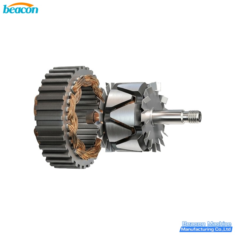
Walk into any industrial motor rewind shop at 7 AM and you will hear the same sound every senior technician already knows: the rising whine of a rotor being spun up on a balancing machine. That sound tells you whether a freshly rewound medium motor, a CNC servo spindle, a torque motor off a packaging line, or a brake-motor rotor will run for the next five years — or come back inside twelve months with noisy bearings, a hot housing, or a tripped inverter. Behind that sound is a deceptively simple question: does every point on the rotor have the same mass as the point diametrically opposite it? If the answer is no, the rotor will shake. The bearings will wear. The winding insulation will crack. The servo loop will oscillate. And the packaging line will start producing wrinkled film and mis-sealed bags.
This guide is written for four very specific jobs that share the same physics but look completely different on the bench:
1. Medium AC motor rotors — IEC 132-280 frame, typically 5-50 kg, used in pumps, fans, conveyors, gearboxes, mixers, hoist motors, brake motors.
2. Servo motor rotors — small diameter (60-180 mm), very low inertia, very high speed (3 000-10 000 rpm), encoder-grade precision.
3. Torque motor rotors — flat disc or cup shape, large diameter, low rpm, used in winding reels, tension stands, extruders, label-feed rollers.
4. Packaging machinery rotors — combination of motor + brake + clutch + fan + pulley, single-plane disc geometry in most cases.
All four job types run into the same family of problems when the rotor is left in its "as-machined" state. The goal of this guide is to explain when balancing is mandatory, what unbalance actually does, how to read the symptoms, and which balancing machine on the BEACON line-up fits each application.
1. What "unbalance" really means on a rotating part
Unbalance is the condition where the center of gravity of a rotor does not lie on the axis of rotation. In a perfect rotor, every gram of mass is placed symmetrically around the shaft. In a real rotor, mass is never perfectly symmetric — there are copper windings, keyways, ventilation holes, balancing rings, shaft steps, rotor bars, magnet pockets, and laminated stack eccentricities. Even an empty shaft turned on a precision lathe will carry a few tens of µm of geometric runout, which translates into gram-millimetre level unbalance once the rotor bars and shorting rings are added.
There are three families of unbalance a workshop needs to recognise:
— Static unbalance — the heavy spot is at one end of the rotor, the light spot is on the opposite side. The rotor behaves like a one-sided pendulum. It will "sit" with the heavy spot down when placed on two knife-edges. Single-plane balancing is enough to fix this case.
— Couple unbalance — two heavy spots, one at each end, on the same side. The rotor does not "sit" on knife-edges, but it will rock end-to-end. This requires two-plane balancing because the heavy spots are 180° apart axially.
— Dynamic unbalance — the general case: heavy spots can be at any axial position, any angular position, and there may be multiple of them on a laminated rotor. Two-plane balancing is required.
The workshop reality: most medium-motor and packaging rotors that come back from the winding shop are dynamically unbalanced, even if the assembler only sees a static wobble.
2. Why these four rotor families must be balanced before delivery
A medium motor rotor left with 50-100 g·mm of residual unbalance will appear to run fine on no-load. The day a coupling is fitted to a gearbox, the unbalance multiplies through the drivetrain. Symptoms appear within weeks:
— Bearing inner-race spalling (premature failure at 6-14 months)
— Vibration trip on the inverter (especially with modern VFDs that sample current ripple)
— Loose winding wedges on the stator (vibration migrates through the air-gap field)
— Acoustic noise 8-15 dB above the smooth-running reference
— Stator-to-rotor rub during starting transients, which destroys the winding insulation in one event
Servo motor rotors are different again. They spin faster, they have lower inertia, and the encoder reports back to a closed-loop controller. An unbalanced servo rotor will:
— Limit the achievable velocity loop bandwidth
— Produce a 1× running-speed tone that contaminates the FFT and confuses vibration-monitoring software
— Drift the spindle centre during cutting, which translates directly into surface finish errors
— Invalidate any Class A surface-grading pass
Torque motor rotors are physically large and physically short. Their polar moment is very high. An unbalanced torque rotor will:
— Generate a constant torque ripple on the load (this is the worst symptom — it shows up as banding on wound film, uneven tension on fabric, and inconsistent torque on the take-up reel)
— Cause the bearing housings to walk sideways on the mounting feet
— Pre-load the gear teeth on the in-line planetary gearbox, accelerating pitting
Packaging machinery rotors are usually disc-shaped and short in length. They carry the brake disc, the clutch plate, the cooling fan and a pulley on the same shaft. Each of those items adds asymmetric mass, and the cumulative unbalance adds up. Unbalanced packaging rotors stop the line with:
— Misaligned conveyor belts
— Mis-sealed bags
— Worn brake linings within a month
— Labelling heads drifting in and out of register
3. Features that always identify a rotor that needs balancing
Most rotors carry several "tells" that warn the workshop that balancing is mandatory:
— Laminated rotor core with skewed slots — skewed slots are used to reduce cogging torque, but every skewed slot produces a small axial shift of the centre of gravity. The heavier the stack (over 8-10 kg), the more the cumulative offset.
— Cast-aluminium rotor bars with end-rings — the end-rings cannot be machined symmetrically because the casting process leaves a heavier side where the molten metal filled last.
— Shaft steps and shoulders — every transition from one shaft diameter to another is an axial step. If the rotor bars and the fan are on opposite sides of the step, the rotor carries a built-in couple unbalance.
— Mounted fan or impeller — fans and impellers are inherently asymmetric. Even a clean impeller carries 5-20 g·mm of residual unbalance, which is acceptable only if the rotor it is mounted to has the opposite pre-balance built in.
— Windings, magnets or pole-pieces assembled off-centre — this is the biggest contributor in torque motors and servo motors. Any magnet pocket that is filled off-centre by 0.1 mm moves 50 g·mm of effective unbalance in a 100 mm diameter rotor.
— Brake disc, clutch plate, pulley, encoder, tachometer — each one is a separate asymmetric mass added to the shaft. A brake-motor rotor with brake disc + fan + pulley + half-key is essentially a textbook case for two-plane balancing.
— Service-repaired rotors — every welding repair, every keyway re-cut, every new bearing journal adds asymmetry. A rotor that was in spec ten years ago is no longer in spec after a rewind.
The simple rule: if the rotor carries any two of the items above, it must be balanced before it goes back into service.
4. ISO 1940 balance grades — which grade fits which rotor
ISO 1940-1 defines balance quality grades for rigid rotors. The grade letter (G) corresponds to a permissible specific unbalance e·ω in mm/s. The grade you pick depends on the rotor type and the service speed:
— Medium AC motor (2-pole, 3 000 rpm): G 2.5 (2.5 mm/s)
— Medium AC motor (4-pole, 1 500 rpm): G 6.3 (6.3 mm/s)
— Servo motor (high speed, encoder feedback): G 1.0 (1.0 mm/s)
— Torque motor (low speed, large diameter): G 6.3 (6.3 mm/s)
— Packaging machinery rotor (disc, 1 500 rpm): G 6.3 (6.3 mm/s)
— Pump and fan rotor (close-coupled): G 2.5 (2.5 mm/s)
— Brake-motor rotor with disc: G 2.5 (2.5 mm/s)
A workshop running G 2.5 on a servo motor will be rejected by the customer — the encoder-grade loop sees the residual vibration as a control error. A workshop running G 16 on a medium motor is leaving money on the table — bearing life roughly halves for every doubling of vibration amplitude.
5. How rotors are balanced — static, single-plane, two-plane
Three methods cover 95% of workshop balancing work:
— Static balancing on knife-edges — the rotor is placed on two parallel hardened rails. Gravity rotates the rotor so the heavy spot points down. This method is suitable only for thin disc-type rotors (fans, brake discs, clutches, flywheels). It does NOT detect couple unbalance. It is also dangerous on rotors over 20 kg without a safety frame.
— Single-plane dynamic balancing — the rotor is spun on a horizontal balancing machine, the vibration sensor reads the 1× running-speed component, the software calculates the magnitude and angle of the heavy spot, and a correction mass (or a material removal) is applied in the correction plane. Suitable for disc rotors, fans, pulleys, brake discs, clutch plates.
— Two-plane dynamic balancing — two correction planes, one at each end of the rotor, are measured independently. Suitable for rotors with axial length greater than one-third of the diameter (typical for medium AC motors, servo motors, torque motor armatures).
The minimum residual unbalance achievable on a workshop balancing machine is roughly 0.5-1.0 g·mm/kg, depending on the spindle stiffness, the sensor noise floor, and the operator's discipline.
6. Choosing the right BEACON balancing machine
BEACON builds the YYQ line of horizontal hard-bearing dynamic balancing machines, plus the RYQ series for turbochargers and the dedicated single-plane vertical machines for disc rotors. The selection rule is straightforward:
— YYQ-16 — workpieces 0.3-16 kg, max diameter 400 mm. Servo motor rotors, small torque motor armatures, encoder rotors, small brake discs, clutch plates.
— YYQ-50A — workpieces 2-50 kg, max diameter 600 mm. Medium AC motor rotors up to IEC 160 frame, packaging machinery rotors, fan rotors, pump rotors, small brake-motor rotors.
— YYQ-100S / YYQ-100L — workpieces 2-100 kg, max diameter 900 mm. IEC 180-225 medium AC motor rotors, large packaging rotors, hoist motors, gear motor rotors.
— YYQ-160A Series — workpieces 5-200 kg, max diameter 1 100 mm. IEC 250-280 medium AC motors, large torque motor rotors, mid-size industrial fan rotors.
— YYQ-200S / YYQ-500S / YYQ-1000A / YYQ-3000S — 200 kg up to 3 000 kg. Large industrial motor rotors, generator rotors, large fan and turbine rotors.
— RYQ-3A — turbocharger-specific, high precision at low mass.
— Single-plane vertical balancing machine — pure disc rotors (brake disc, clutch plate, flywheel) on a vertical mandrel with a single correction plane.
The YYQ series uses belt (ring-belt) drive for low-speed rotors (200-1 500 rpm) and universal-joint drive for higher speeds, with a 32-bit industrial PC, dedicated BEACON balancing software, piezoelectric vibration sensors, and an INVT frequency converter for smooth ramp-up. Minimum achievable residual unbalance ≤ 0.5 g·mm/kg, unbalance reduction ratio ≥ 90% — comfortably meeting ISO 1940-1 G 1.0 to G 6.3 across the rotor range described above.
7. Practical workflow on a BEACON YYQ-50A for a medium motor rotor
1. Mount the rotor on the swing-frame rollers, level the lathe bed, set the safety enclosure.
2. Enter the rotor mass, journal diameters, distance between the two correction planes, and the rotor length into the BEACON software.
3. Run a low-speed spin (300-500 rpm) to confirm the pickup signal and the reference mark are clean.
4. Run the first calibration trial mass on the left plane — the software displays the trial unbalance value.
5. Run the calibration trial on the right plane.
6. Spin the rotor at working speed (typically 900-1 500 rpm for a 4-pole motor), the software displays the magnitude and angle of unbalance at each plane in real time.
7. Apply correction mass (welded, bolted, or drilled) on each plane at the indicated angle.
8. Spin again to confirm the residual unbalance is within grade — for a 4-pole medium motor the target is ≤ 6.3 g·mm/kg (ISO G 6.3).
9. Print the balance report and attach to the rotor history file.
The full cycle on a medium motor rotor is typically 8-15 minutes once the operator is trained. For a packaging line producing 40-80 brake-motor rotors per shift, two YYQ-100S machines side-by-side are the standard configuration.
8. What to do when a rotor keeps failing balance
A small percentage of rotors will refuse to drop below grade no matter how many times the trial mass is moved. The usual causes:
— Bent shaft — the shaft itself is bent (over 0.05 mm runout at mid-span). Straighten on a hydraulic press before balancing.
— Loose lamination stack — the rotor bar end-rings are not fully seated against the lamination stack, so the rotor mass distribution shifts during spinning. Tighten or re-cast before balancing.
— Soft-bearing resonance — the swing-frame natural frequency is too close to the running speed. Adjust the bearing pad position or change the swing-frame stiffness.
— Sensor cable routing — the cable runs too close to the drive motor or the VFD, picking up electrical noise. Re-route away from the power cables.
These four faults will produce a balance result that is mathematically "in spec" on the screen but physically wrong. Always cross-check the displayed unbalance against a simple knife-edge check before accepting the result.
9. Recommended BEACON equipment for the four rotor families
— Servo motor rotors: YYQ-16, RYQ-3A (0.3-16 kg, belt or universal joint)
— Torque motor armatures (small): YYQ-16, YYQ-50A (2-50 kg, belt)
— Torque motor armatures (large): YYQ-100L, YYQ-160A (5-160 kg, belt)
— Medium AC motor rotors (IEC 132-180): YYQ-50A, YYQ-100S (2-100 kg, belt or universal joint)
— Medium AC motor rotors (IEC 200-280): YYQ-160A, YYQ-200S (5-200 kg, belt or universal joint)
— Packaging machinery brake/clutch rotors: YYQ-16, YYQ-50A, single-plane vertical (0.3-50 kg, belt)
— Packaging machinery fan rotors: YYQ-100S, YYQ-100L (2-100 kg, belt)
— Hoist / gear motor rotors: YYQ-100L, YYQ-160A (2-160 kg, belt)
For a workshop that rebalances a mix of servo, torque, medium-motor and packaging rotors, the most flexible single-machine choice is the YYQ-50A — its 0.3-50 kg range, 600 mm diameter capacity, and ISO G 1.0 achievable grade covers the majority of these jobs.
Picture guide — which BEACON machine for which rotor family (click the picture to open the product page):
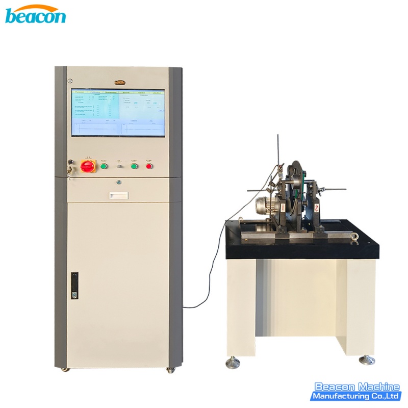
YYQ-16 — servo motor rotors and small torque motor armatures (0.3-16 kg)
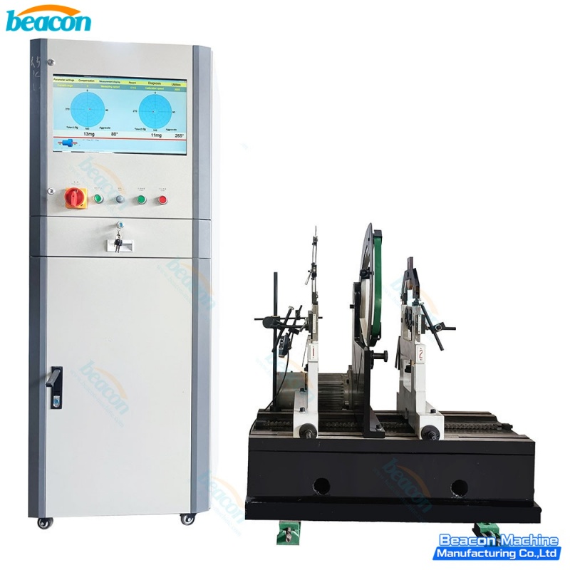
YYQ-50A — medium AC motor rotors IEC 132-180 and packaging machinery brake/clutch rotors (2-50 kg)
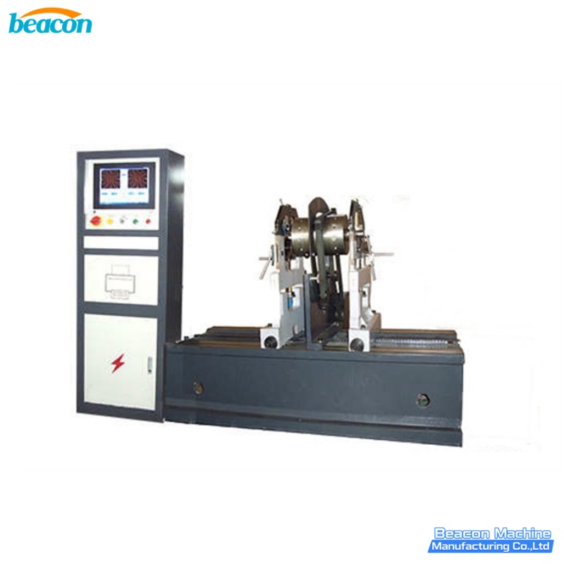
YYQ-100S — IEC 200-225 medium AC motors and packaging fan rotors (2-100 kg)
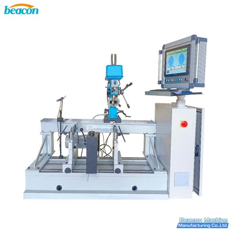
YYQ-100L — hoist motors, gear motors, packaging rotors with integrated drilling (2-100 kg)
10. Closing note
Rotor balancing is one of those workshop operations that everybody talks about and very few people actually measure. The shops that do measure it — and that keep the balance report on file for every rotor that leaves the bench — are the shops whose motors come back inside 24 months instead of 12. The investment is a single horizontal balancing machine, two operators trained on the BEACON software, and one printed report per rotor. The return is fewer warranty claims, fewer inverter trips, and a better reputation with the OEM customers who eventually write the spec.
For full specifications on the BEACON YYQ series, see the product pages below or contact BEACON MACHINE for a quotation tailored to your rotor mix.
11. Related BEACON products
Each machine is a real BEACON YYQ-series horizontal hard-bearing dynamic balancing machine. Click the picture to open the product page, or click the model code below the picture.
YYQ-16 — small rotor balancer (0.3-16 kg): /Product/YYQ-16-Series-General-Horizontal-Hard-Support-Dynamic-Balancing-Machine-Industrial-Rotor-Balancer.html
YYQ-50A — medium rotor balancer (2-50 kg): /Product/YYQ-50A-Horizontal-Hard-Support-Dynamic-Balancing-Machine-Industrial-Rotor-Balancer.html
YYQ-100S — medium-large rotor balancer (2-100 kg): /Product/YYQ-100S-Dynamic-Balancing-Machine-Belt-Drive-Hard-Bearing-Balancer-for-Rotors-Motors.html
YYQ-100L — medium-large balancer with integrated drilling: /Product/YYQ-100L-Dynamic-Balancing-Machine-with-Integrated-Drilling-Machine-Belt-Drive-Hard-Bearing-Balancer.html
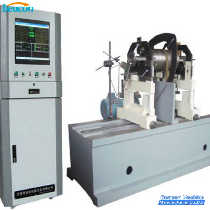
YYQ-160A Series — large rotor balancer (5-200 kg): /Product/YYQ-160A-Series-Horizontal-Hard-Bearing-Dynamic-Balancing-Machine-Universal-Rotor-Balancer.html
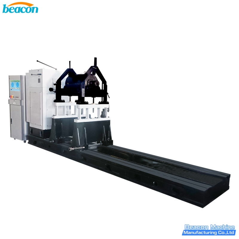
YYQ-3000S — heavy industrial rotor balancer (50-3 000 kg): /Product/YYQ-3000S-Universal-Dynamic-Balancing-Machine-Horizontal-Hard-Support-Rotor-Balancer.html
References
— ISO 1940-1:2003 — Mechanical vibration — Balance quality requirements for rotors in a constant (rigid) state.
— GB/T 4201-2006 — Balance quality requirements for rigid rotors (Chinese standard, equivalent to ISO 1940-1).
— BEACON MACHINE YYQ-100 product specification document, 2025.
BEACON MACHINE - Jinan Beacon Machine Co., Ltd.
WhatsApp / Tel: +86 186 6373 7682
Email: export@beaconmachine.com
Website: www.taianbeaconmachine.com