Language
  EN
EN RU
RU ES
ES DE
DE EL
EL IT
IT JA
JA KO
KO PT
PT ID
ID SR
SR UK
UK VI
VI TH
TH TR
TR MS
MS BE
BE AR
ARAlternator Rotor Balancing: Why It Matters and How to Do It
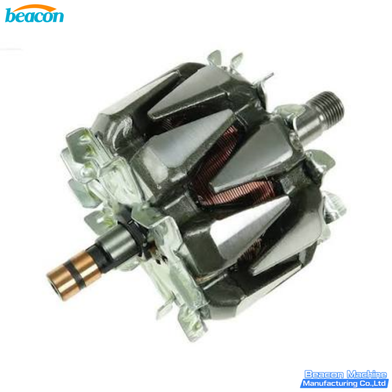
Walk past any alternator rebuild shop at 8 AM and you will hear a sound every rebuilder knows but most drivers do not: the high-pitched whine of a rotor being spun up on a balancing machine. That is the moment when a "warranty-return" alternator either earns another year of service life or goes straight to the scrap bin. Behind that sound is a deceptively simple question — does every point on the rotor have the same mass as the point diametrically opposite it? If the answer is no, the rotor will shake, the bearings will wear, and the diodes will fail.
Almost every automotive electrical failure that gets blamed on "the battery" or "the regulator" actually starts as an unbalanced rotor. This guide explains what alternator rotor imbalance is, how to detect it, how to fix it, and when a rotor is beyond saving. It is written for rebuilders, automotive electrical workshops, generator service shops, and the engineering students who end up working in them.
1. What a Claw-Pole Alternator Rotor Actually Is
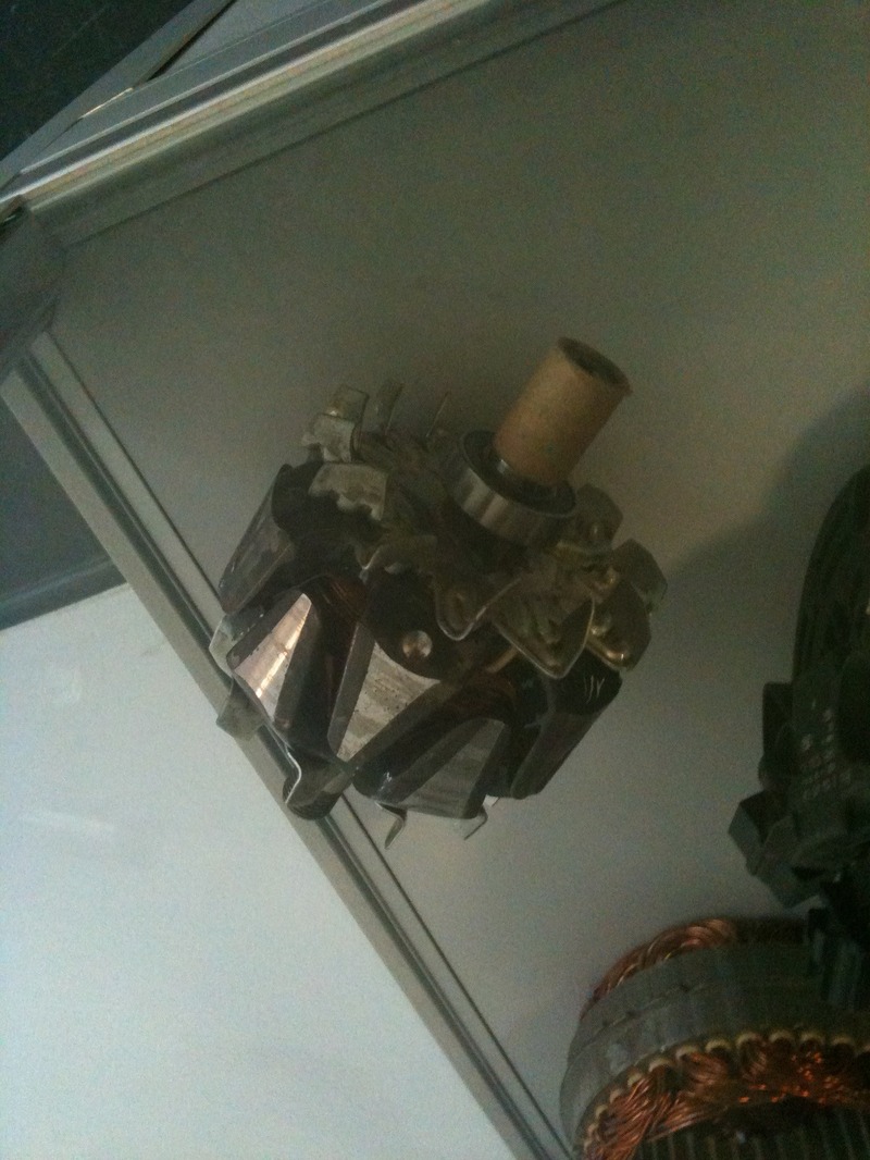
Almost every automotive alternator from the 1960s onward uses a Lundell (claw-pole) rotor. Two stamped steel halves with interlocking finger-shaped pole pieces clamp a field winding between them. When the slip rings — those two copper bands on the rotor shaft — feed DC to that winding, the pole pieces become electromagnets. The surrounding stator then generates three-phase AC, which the rectifier bridge turns into the DC that charges the battery.
The rotor is therefore the only moving part inside the alternator that has a meaningful axial footprint. The shaft is small in diameter, the pole pieces extend radially, and the slip rings add an asymmetric mass at one end. That geometry is the reason every claw-pole rotor leaves the factory with a specific mass distribution burned into a process specification.
Key rotor components that matter for balancing:
Rotor core (claw-pole halves): Two stamped steel pieces with 6 or 7 claw poles each. Any burr, flash, or weld spatter on these poles shifts the mass centerline.
Field winding: Copper wire bobbin-wound on the rotor shaft. Density variation between batches causes inherent imbalance.
Slip rings: Two copper rings brazed onto the rear of the shaft. Machining tolerances typically leave 5-15 g·mm of residual imbalance.
Shaft: Forged steel, ground to tolerance. The most common source of catastrophic imbalance when worn or bent.
Cooling fan: Usually integrated with the rotor or pressed onto the shaft. A broken fan blade creates severe one-sided imbalance.
2. Why Rotor Imbalance Matters More Than People Think
An automotive alternator spins at 6,000 to 18,000 RPM depending on engine speed and pulley ratio. At those speeds, even a small mass offset creates centrifugal force proportional to the square of the RPM. Doubling the speed quadruples the force. A 10 g·mm imbalance at 6,000 RPM becomes a 40 g·mm force at 12,000 RPM.
That force transfers to the front and rear bearings as vibration. The bearings are the alternator's most maintenance-sensitive components because they must support the rotor, locate it axially against the spring-loaded brushes, and absorb the magnetic pull from the stator. Once the bearings begin to wear, the rotor's orbit grows, the slip rings wear unevenly, and the brushes start chattering. The driver notices this as a noisy charging system or a flickering dashboard voltmeter.
Three failure paths trace directly back to an unbalanced rotor:
Bearing failure. Premature wear of front or rear bearings, usually within 30,000 km on a passenger car.
Slip ring and brush wear. Uneven slip ring surface causes arcing, which pits the copper and accelerates brush wear.
Diode failure. Vibration loosens the rectifier bridge's press-fit diodes. The alternator then begins to leak AC into the DC bus, which can confuse the ECU and damage the battery.
For a heavy-duty truck or coach running a 24V 110A alternator, the same physics applies but the stakes are higher. A roadside breakdown costs far more than a workshop rebuild.
3. The ISO 1940 Balance Quality Standard You Should Be Working To
The international reference for balance quality is ISO 1940-1, now harmonized as ISO 21940-11. The standard defines balance quality grades G 0.4 through G 4000, where the grade number is the maximum permissible residual specific unbalance in mm/s, measured at the nominal running speed.
For automotive alternators, the relevant grade is typically G 6.3 for the rotor as a standalone component, and G 16 to G 40 for the complete alternator as installed. A passenger-car claw-pole rotor weighing 4 kg at 6,000 RPM operating speed would target a residual unbalance no greater than roughly 25 g·mm per correction plane.
What this means in workshop terms: a rotor that leaves the bench with more than 25 g·mm residual imbalance is technically out of specification. The customer may not notice immediately, but the bearings and brushes will absorb the punishment over the next 20,000 to 40,000 km.
4. How to Diagnose a Rotor Balance Problem in the Workshop
Before sending any rotor to the balancing machine, the diagnosis should follow a fixed sequence. Skipping steps is the most common cause of "I balanced it but the vibration is still there" rework.
Step 1 — Visual inspection. Look at the rotor in good daylight. Check the fan blades for chips or cracks, the claw poles for bent fingers, the slip rings for grooving or burn marks, and the shaft for any visible runout when rolled on a flat surface.
Step 2 — Runout check. Mount the rotor between centers on a lathe or V-blocks with a dial indicator on the slip ring surface and the pole face. Total indicated runout above 0.05 mm on the slip rings or 0.08 mm on the pole faces points to a bent shaft, not a balance issue.
Step 3 — Bearing inspection. Spin the rotor by hand with the bearings installed. Any grittiness, roughness, or binding means the bearings need replacement before any balancing attempt. Balancing a rotor on worn bearings produces a false reading because the bearing vibration contaminates the measurement.
Step 4 — Electrical check. Measure rotor field winding resistance with a multimeter. A typical claw-pole rotor reads between 2.0 and 5.0 ohms across the slip rings. Open circuit (infinite resistance) means the winding is broken; zero resistance means a short. Either condition requires rewinding or replacement before balancing.
Step 5 — Test on the balancing machine. Only after the four prior checks pass should the rotor go on the balancing machine. If the rotor fails on steps 1-4, no amount of balancing will make it a good unit.
5. Choosing the Right Balancing Machine for Alternator Rotors
An alternator rotor is one of the easier rotors to balance, but only if the machine is appropriate. There are four machine architectures and three of them are wrong for this job.
Belt-drive dynamic balancing machines (YYQ-series, belt drive) are the standard choice for rotors up to about 100 kg. The belt couples the drive motor to the rotor through a flat or V-belt. This isolates the drive vibration from the measurement, gives accurate readings at low and medium speeds, and supports rotors with shaft diameters from 10 mm upward. The YYQ-50A horizontal hard-support dynamic balancing machine covers rotors from 3 to 50 kg, which is the typical range for passenger-car and light-truck alternators.
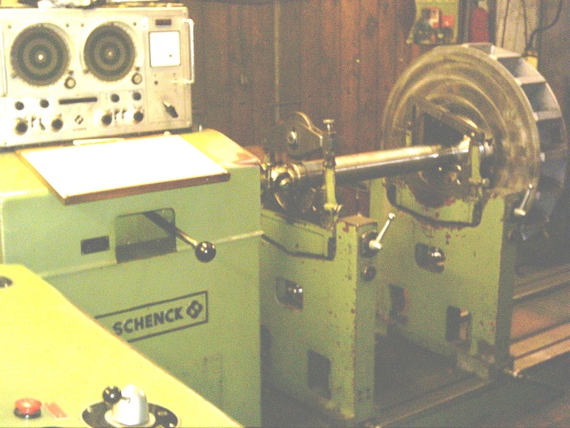
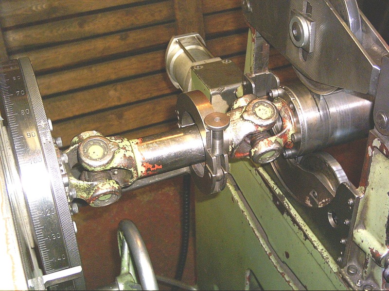
Universal-shaft (cardan) balancing machines (YYW-series) are required when the rotor cannot be supported on its own shaft journals, or when the rotor is too heavy for belt drive. They drive the rotor through a universal joint at one end and support the other end on a roller or bearing pedestal. This is the architecture used in the photo below, with a drive shaft being balanced on a horizontal machine. For heavier rotors or for rotors with non-standard shaft ends, a universal-shaft machine is the right choice. The 30 kg to 50 kg working range overlaps with the upper end of alternator rotors but extends well into the industrial motor range.
Vertical single-plane balancing machines (YLD-series) are designed for disk-shaped rotors — flywheels, brake discs, clutch plates, pulleys. They are not appropriate for a long, slender claw-pole rotor because the rotor geometry does not match the machine's measurement kinematics.
Wheel balancing machines (the kind used in tire shops) are designed for vehicle wheels and tires. They cannot measure a rotor's two correction planes accurately because the rotor's shaft is much smaller than a wheel hub.
For an alternator rebuilder, the practical recommendation is: a belt-drive machine in the 3 to 50 kg range for the bulk of automotive alternators, with a heavier universal-shaft machine available for industrial and heavy-truck rotors.
6. The Balancing Procedure Step by Step
Once the rotor is on the machine, the procedure follows a fixed six-step flow. Each step has a specific purpose and a specific output.
Step 1 — Mount the rotor on the machine. Place the rotor on the belt-drive rollers or between the universal-joint supports. Confirm the shaft journals are clean and free of nicks. Adjust the belt tension so the rotor can be spun up without slipping.
Step 2 — Set up the measurement parameters. Enter the rotor mass, the distance between the two correction planes, the rotor diameter, and the target balance grade. The machine uses these to calculate the permissible residual unbalance per plane and the display scaling.
Step 3 — Run the rotor up to test speed. Bring the rotor up to the test speed specified by the machine's setup. For an alternator rotor, this is usually between 800 and 1500 RPM — well below the operating speed but high enough for the measurement system to lock onto the unbalance signal.
Step 4 — Read the unbalance values. The display shows two values: the amount of unbalance in g or g·mm at each correction plane, and the angular position of the heavy spot. Modern machines show both planes simultaneously, which allows a single correction pass.
Step 5 — Apply the correction. There are three correction methods. Drilling removes material from the light side. Welding adds material to the light side. Press-fitting inserts a balance clip or weight. For claw-pole rotors, the standard practice is to drill a hole in the heavy-side claw pole finger to a controlled depth and diameter specified by the rotor manufacturer.
Step 6 — Verify. Run the rotor again, measure the residual unbalance, and confirm it is below the target threshold. A typical acceptance criterion for a passenger-car claw-pole rotor is below 10 g·mm per plane at the test speed.
7. Correction Methods in Detail
The three correction methods each have advantages and constraints. Choosing the wrong one can make the imbalance worse.
Drilling is the most common method for claw-pole rotors because the pole pieces are already thick enough to accept a small drilled hole without weakening the magnetic structure. The drill diameter is typically 6 to 8 mm and the depth is 4 to 6 mm. The location is critical — the hole must be on the heavy-side pole finger at the radial position indicated by the machine. Drilling on the wrong side makes the imbalance worse.
Welding is used when drilling would weaken the pole piece or when the rotor is a one-off prototype with no manufacturer drilling specification. The weld material is typically a low-carbon steel rod applied with a TIG or MIG process. The weld must be ground smooth and checked for cracks before the rotor is approved.
Balance clips or weights are rarely used on claw-pole rotors because there is no flat surface to attach them. They are more common on flywheel-type rotors where a counterweight ring is part of the design.
The general rule: always remove material from the heavy side, never add material to the light side, unless the rotor design specifically allows it. Removing material reduces the rotor mass slightly, which is usually insignificant for the alternator's electrical performance.
8. Common Mistakes That Make Balancing Fail
After auditing rotor balancing work in rebuild shops for several years, the same five mistakes account for the majority of failed rebuilds.
Mistake 1: Balancing a rotor with worn bearings. The bearing vibration contaminates the measurement and produces an inaccurate heavy-spot reading. The rotor then leaves the bench "balanced" but vibrates in the vehicle.
Mistake 2: Balancing a rotor with a bent shaft. A bent shaft means the rotor's rotation axis is not the geometric center. The balancing machine measures the rotation axis as the reference, so the machine cannot fix what is fundamentally a straightness problem.
Mistake 3: Using the wrong correction plane distance. The two correction planes on an alternator rotor are typically located at the claw pole position and at the slip ring position. Entering the wrong distance shifts the calculated correction amount.
Mistake 4: Running the rotor at the wrong test speed. Some operators run the rotor at full operating speed to "save time." This is unnecessary and can damage the bearings. The test speed is much lower than operating speed, by design.
Mistake 5: Skipping the verification run. A rotor that reads as balanced after one correction pass is not necessarily balanced. The verification run is the only step that catches a misread or a slip during the first correction.
9. When to Replace Instead of Balance
Some rotors are beyond saving and the correct decision is to replace, not rebalance. The decision criteria are:
Shaft runout above 0.08 mm. The shaft is bent and cannot be straightened economically.
Bearing journals scored or worn. A new rotor is cheaper than rebuilding the bearings.
Claw pole fingers broken or chipped. The pole geometry is critical for magnetic performance. Damaged fingers reduce output.
Slip rings worn below minimum diameter. Most manufacturers specify a minimum slip ring diameter below which the rings must be turned down and replaced, or the rotor scrapped.
Field winding open or shorted. Rewinding a rotor is usually more expensive than a replacement rotor from a remanufacturer.
For common vehicles — Ford Focus, VW Golf, Toyota Corolla, Honda Civic — remanufactured rotors are widely available and usually cheaper than the labor to rewind an OEM rotor. For low-volume or specialty applications, rebalancing and rebuilding may be the only option.
10. Bringing It Together in Your Workshop
A well-equipped alternator rebuild station needs three pieces of equipment: a dedicated alternator and starter test bench for electrical performance verification, a belt-drive dynamic balancing machine sized for the typical rotor weight range, and a small parts cleaner plus bearing puller set. For shops that also handle larger commercial vehicle alternators, a heavier-duty belt-drive balancing machine covering up to 100 kg provides the working range to cover everything from motorcycle rotors to light-truck rotors on the same machine.
The diagnostic sequence — visual inspection, runout, bearing check, electrical test, then balance — should be followed on every rotor. Skipping steps turns a 15-minute balancing job into a comeback the next day. The verification run is the step that catches errors before the rotor goes back into a customer's vehicle.
For shops that want to expand into industrial rotors as well, a universal-shaft machine in the 30 to 3000 kg range opens the door to balancing electric motor armatures, pump impellers, and small fan rotors — work that often arrives through the same customer relationships. The same diagnostic discipline applies.
If your team is currently rebuilding alternators by feel or by ear, adding a proper balancing machine is one of the higher-ROI investments available. Warranty returns drop, customer satisfaction improves, and the workshop gains the ability to take on higher-value electrical work. Reach out to our engineering team to discuss the configuration that fits your rebuild volume and rotor weight range.
References and Further Reading
ISO 21940-11:2016 — Mechanical vibration — Rotor balancing — Procedures and tolerances for rotors with rigid behaviour
Bosch Automotive Electric Systems and Components — Rotating machines design and test procedures
Denso Service Information — Alternator disassembly and balance correction
Motorcraft Remanufacturing Manual — Claw-pole rotor balance correction
Related products
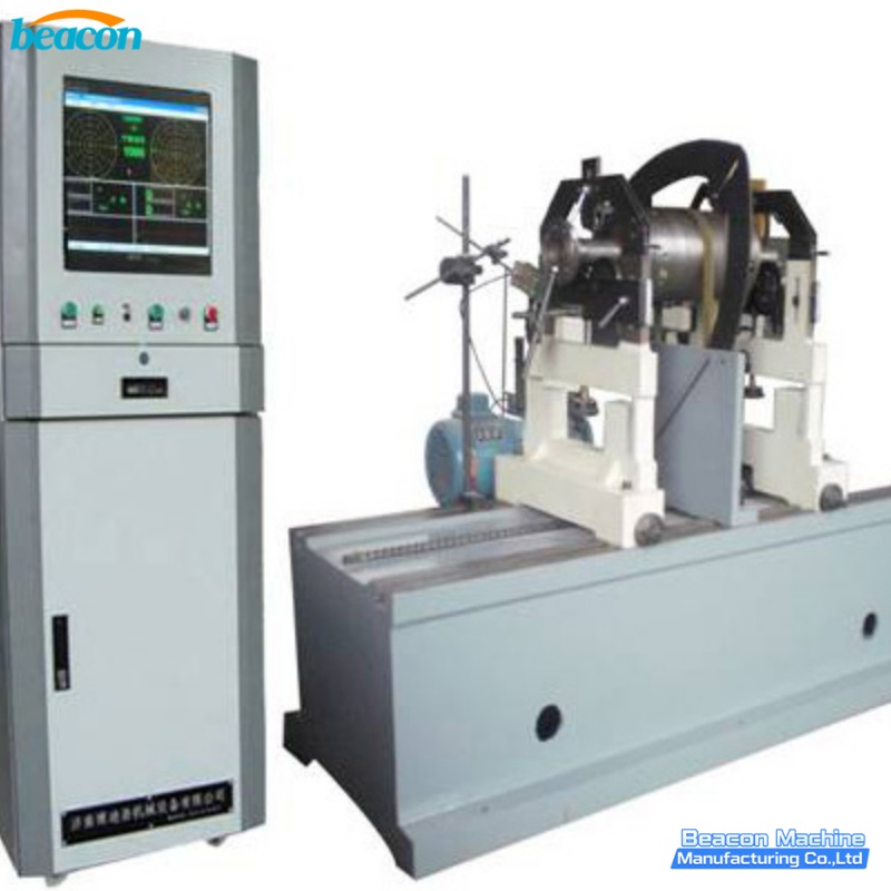
YYQ-160A 160kg Engine Fan Pump Impeller Horizontal Hard-Bearing Dynamic Balancer for Fan Pump Industry

YYQ-100L 100kg Impeller Centrifuge Basket Dynamic Balancing Machine with Integrated Drilling Unit
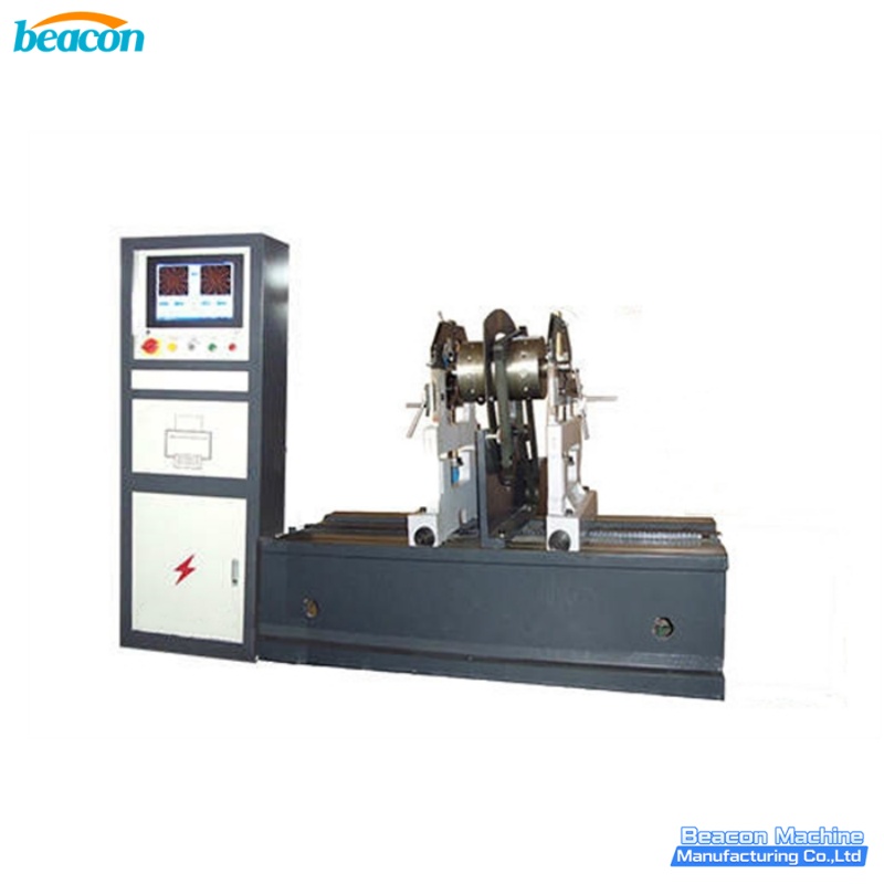
YYQ-100S 100kg Pump Impeller Fan Turbine Dynamic Balancing Machine Belt Drive for Water Pump Fan Industry